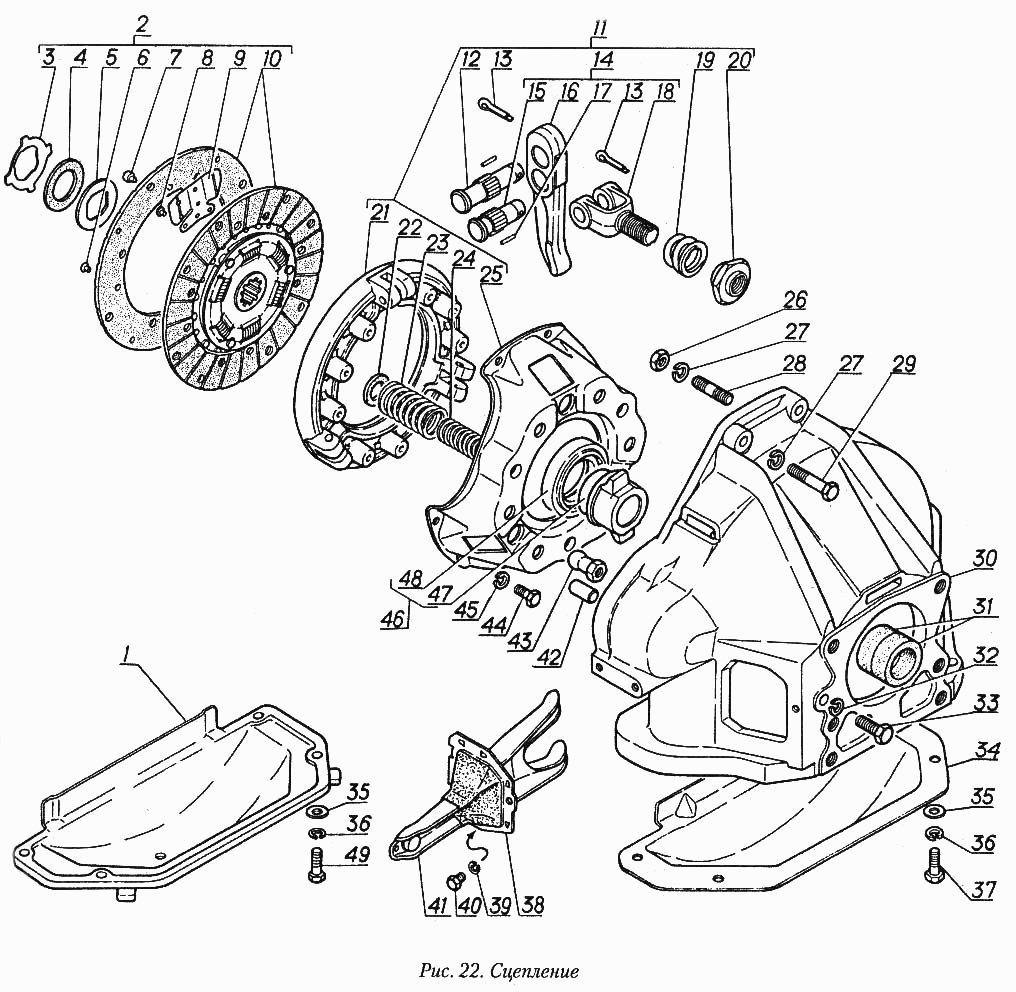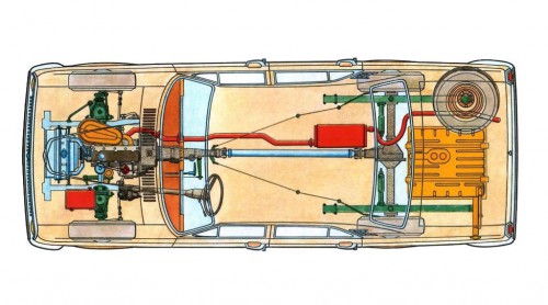
- Coil spring clutch assembly, driven plate 225 mm / 8.8″ in diameter
- Hydraulic clutch linkage (self-adjusting since late 1974)
- 4-speed all-synchromesh manual transmission, floor shift
- Open drive shaft with two universal joints at its ends
- Hypoid rear end, 4.1 ratio (3.9 after 1985), with semi-floating axle shafts
The original clutch is of the older coil-spring type, its basic design probably dating back to before WWII. Depending on your luck, it can either be completely trouble-free for hundreds of thousands of kilometers, or produce all sorts of malfunctions. Proper adjustment of the pressure plate’s release levers is extremely important (it’s only done once, during the initial assembly, but must be done right).
Hydraulic clutch linkage was used, and starting in October, 1974 the slave cylinder was of the self-adjusting type, eliminating any play in the linkage, as well as the need to manually adjust the length of its push rod to compensate for the wear. As a downside, with this self-adjusting linkage the thrust bearing was constantly in contact with the release levers of the clutch pressure plate and wore out somewhat faster, but overall it was a good trade-off.
As the coil-spring clutch was rather stiff by itself, the mechanical advantage of the hydraulic linkage was necessary to make the pedal light enough.
Today, a bolt-on modern, diaphragm-spring type replacement clutch with a stock-sized 225 mm driven plate is available for this car. A larger clutch with a 245 mm driven plate is also available, but in most cases it is required to re-drill the flywheel to install it.
Two bolt patterns were used for this larger clutch assembly, one with 12 bolt holes that is compatible with the old engines (“universal” pressure plate), and the other only has 6 bolt holes and is not compatible (“new-only” pressure plate). The “old” original coil-spring pressure plate had 6 unevenly spaced bolt holes in three groups of two; if the pressure plate has 6 evenly spaced bolt holes – it is not compatible with the old pushrod type Volga engines (flywheel has to be re-drilled to install it).
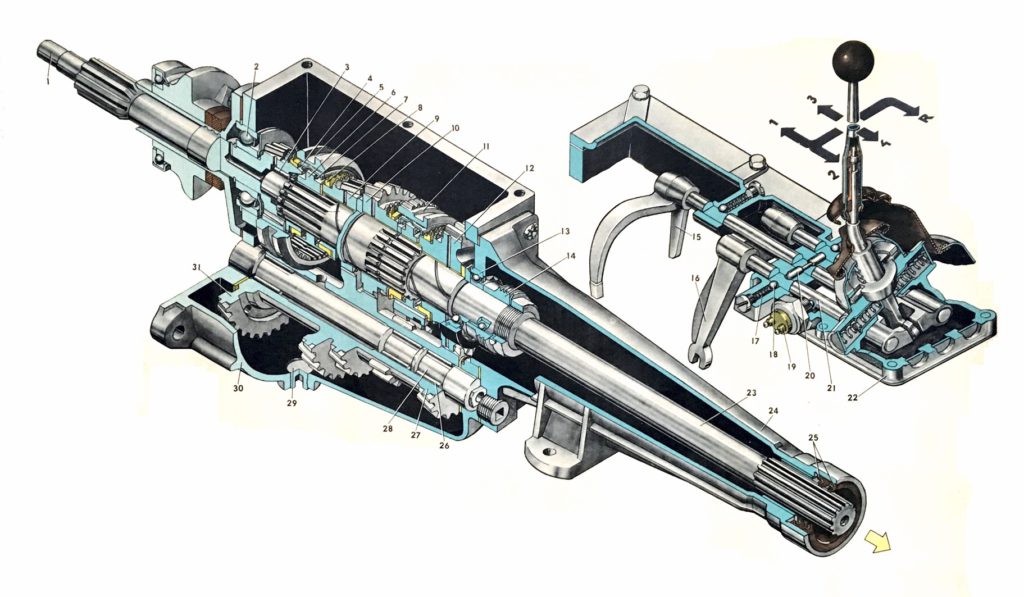
Four-speed, synchromesh on all forward gears. The access cover for the internal components is on top, which adds to the rigidity of the case – an important feature because it is made of aluminum. The shifter is mounted directly on the top cover and is connected with the shift forks by internal shift rails, which provides a very crisp, positive shift feel. A long tailshaft encased in the tail extension housing allowed the use of a one-piece driveshaft instead of a two-piece shaft used on the previous model, which was initially seen as an improvement because of simplicity and durability of the new design.
This gearbox was designed with the 3.0 L V6 in mind, and can manage the torque of a small V8 engine.
Gear ratios were optimized for leisurely driving along half-empty streets, with a very short first gear, which is normally only used for taking off, and a very flexible third gear with a usable range from 15 up to 80 km/h. Fourth gear is direct drive and overdrive was not available.
The one-piece drive shaft taken by itself was a simple and reliable design (unlike the two-piece shaft used on the previous model, which often had problems with its rubber-mounted center support) and also could be removed & installed much easier and faster.
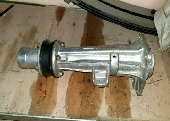
However, initially it became a source of some major problems for the plant, because it took some time to figure out hot to properly balance the driveshaft, and on some cars at a certain combination of wheel and engine speeds (120…130 km/h, 3,800…4,200 RPM) torsional resonances in the driveline were bad enough to make the gearbox tail shaft housing develop some cracks – not to mention annoying the driver.
As a temporary solution, the engineers designed a new tailshaft housing that was split in two pieces, with a thick rubber ring sandwiched between the halves. It served as a damper that suppressed the vibration and changed the resonance characteristics of the driveline, which mostly solved the problem (resonance was now at 80 km/h & 2,600…2,800 RPM, and vibration was much more mild, not causing catastrophic failures). Later on, the balancing of drive shafts improved enough to get rid of it completely and a one-piece tail shaft housing was re-introduced.
The following Volga models eventually received a two-piece driveshaft, not dissimilar to the one used in GAZ-21, but with the center support of an improved design (derived from the GAZelle light truck).
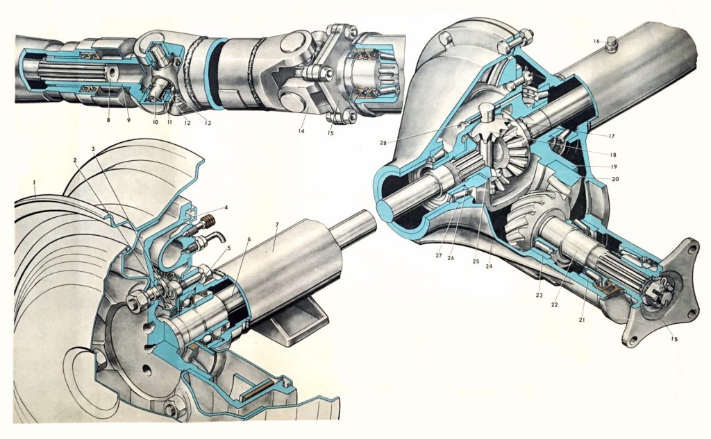
The rear axle is of a rarely used split-case type, which is sometimes called the “Timken axle”. This design, more often found in trucks than in cars, was used because at some point in mid-1950s the GAZ was having troubles with casting one-piece axle housings for GAZ-21 – too many castings had to be scrapped because of casting defects, which was kind of okay for the low-volume ZIM GAZ-12 which also used the design, but was deemed unacceptable for the mass-produced Volga. The split case was seen as a “temporary” solution initially, but, for some reason, the plant decided to stick to this design for quite some time.
Overall, the axle is durable & rarely gives any trouble other than a barely noticeable howling noise at high speed caused by the meshing of the gear set in the differential, which is characteristic of the design and usually not a symptom of any problem.
Gearing was 4.1:1 for GAZ-24 and 3.9:1 for subsequent models. V8 powered cars used the same rear axle, but with taller gearing (3.38:1).

