
GAZ-24 originally used a “point-type” ignition system (also known as the Kettering ignition system), which is a purely mechanical system without any electronic components. While simple, it can be quite tricky to properly tune, and most modern car mechanics are just not familiar with this type of ignition systems, because all modern cars have computer-controlled electronic ignition which by itself completely controls ignition timing and needs little, if any, adjustments at all. However, with some know-how, the necessary adjustments can be done by the owner of the car himself without too much difficulty.
If you are completely unfamiliar with this type of ignition systems in general, there is a good article about it on another website.
GAZ-24-10 received electronic point-less ignition system with a magnetic pick-up sensor, which is by far not pointless and, in fact, much better then the previously used one, and absolutely can be recommended as a simple bolt-on upgrade for the early cars.
Correct ignition timing is extremely important for the correct functioning of the engine and overall performance of the car.
The most important part of the ignition system is the distributor, which, as the name implies, distributes the spark (high voltage current) between the cylinders of the engine, determining which of the spark plugs will receive it. It is also used as a sensor to monitor the position of the crankshaft (and, therefore, the pistons) for proper ignition timing.
Dwell angle is adjusted by changing the gap between the points (the larger the gap, the smaller is the dwell angle – and vice versa).
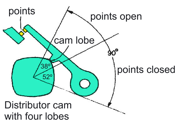
The distributor cam has 4 lobes, corresponding to 4 cylinders of the engine. Each lobe has its own dwell angle, but, as there is only one set of points, the same adjustment will work for all of them.
In the point-type ignition system, the ignition points are used for this purpose, which are basically a pair of electrical contacts that switch the ignition coil on and off at the proper time. The time period during which the ignition coil is turned on, storing electric energy for the spark, is called “dwell“. Dwell is measured as an angle that the distributor cam moves through with the ignition points closed.
The spark is generated at the moment when the ignition points open and the energy stored in the coil is released and transferred to the spark plug.
Adjusting dwell angle is very important and it must be done before any other adjustments of the ignition system, because it will affect the ignition timing.
For the engine to work correctly, the fuel-air mixture in its cylinders must be ignited by the spark at a very specific moment in time – when the piston in the cylinder that is going to get the spark is almost at the Top Dead Center (TDC), but not yet. That’s when ignition timing advance comes into play.
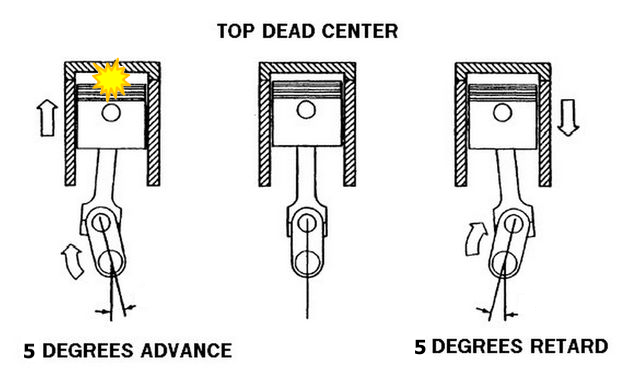
The number of degrees of the crankshaft rotation before Top Dead Center (BTDC) that the spark will ignite the fuel-air mixture is called the “timing advance“.
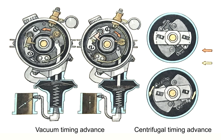
The distributor provides three types of timing advance: initial, or base advance, vacuum advance, and mechanical, or centrifugal advance. Only base timing advance is adjustable, and the other two settings are handled completely automatically, based on engine RPM and the level of vacuum in its intake manifold.
For the GAZ-24 engine, base timing advance should be 5 degrees BTDC (in crankshaft degrees). The centrifugal regulator increases the advance as the engine speed increases. The vacuum diaphragm advances the timing when vacuum is applied to the unit (which happens while the engine works under light load), and retards it when the vacuum reduces (while the engine is working hard under load) – that helps to prevent detonation (engine knocking) under load.
Firing order is 1-2-4-3, number one terminal is usually marked on the distributor cap (if it’s not – it is the left-most of the two terminals that are located adjacent to the vacuum advance diaphragm).
Now, to the adjustment procedure.
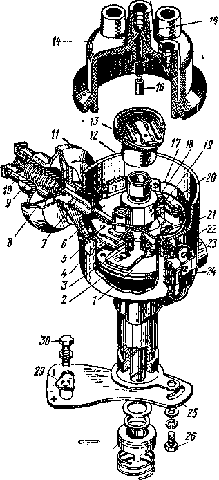
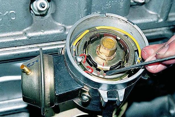
First of all, check the distributor; the rotor should not have any “play” in the shaft from worn bushings and the points have to be nice and clean. The distributor cap (14) should have no cracks or burns, and the contacts, including the spring-loaded carbon central contact (16), should be clean and undamaged. If needed, clean the points and the contacts with a very fine sanding paper, or replace the cap and the points with brand new ones.
Remove the rotor head (13) and adjust the ignition points.
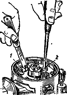
1 is the stop screw that should be loosened for this adjustment, and 2 is the adjustment screw.
When the adjustment is finished, tighten the stop screw.
The correct gap between the ignition points is specified to be 0.35-0.45 (use a feeler gauge to measure), however it can only be correctly measured if the points are almost brand new. If they did work for some time, the surface of the points will be heavily eroded (have pitting and cratering) and the measuring will be incorrect.
Some polishing with a fine sanding paper may help, but the preferable way to do this adjustment would be to measure and set the dwell angle directly. A special device called the dwell meter is used for this. Spec is 52±3º.
When the adjustment is completed, put the rotor back in and install the distributor cap, reconnect the ignition wires.
Remove the spark plugs and check the gap, it should be 0.8-0.9 mm (0.31-0.35 in). Clean and re-gap the plugs if necessary. Put the plugs back in, except for the first cylinder plug (later we’re going to use the spark plug hole to determine when the compression stroke starts in the first cylinder).
Unplug the vacuum advance hose, or unscrew the vacuum advance line, if the original hard line is still used, from the distributor, and plug it so that it doesn’t leak vacuum.
Now we’ll have to identify the beginning of the compression stroke in the first cylinder, because that’s the stroke during which the fuel-air mixture is ignited. The simplest way to do that is to plug the spark plug hole of the first cylinder (which we’ve intentionally left empty earlier on) with you finger (I’m not joking) and to turn the crankshaft clockwise until you feel compressed air coming out of the plugged hole – that’s when compression starts. You can use the starting handle that every Volga car is conveniently equipped with to turn the crankshaft directly, or just grab the cooling system fan and turn it slowly (the belt has to be properly tightened). If you really want to do it the fancy way, you can plug the hole with some paper ball or cork – when compression starts, it will pop out.
What you do next depends on the particular model of engine you car has.
24D / 2401 engine:
There are two notches on the crankshaft pulley, these are your timing marks. The first notch (right-most, if you are looking at it standing in front of the car) corresponds to the first cylinder piston being 5 degrees before Top Dead Center (TDC), and the second notch is TDC.
Keep turning the crankshaft clockwise, very slowly and carefully, until the first notch on the pulley is exactly in line with the pointer needle.
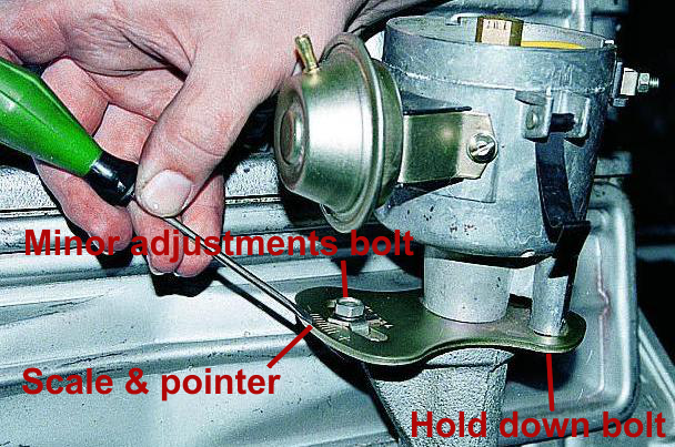
Loosen the minor adjustments bolt (30) slightly. By turning the distributor, set the pointer (29) at Zero on the scale (halfway between “+” and “-“) – that is not the adjustment itself, but will give you a good reference point for minor ignition timing tweaks in the future. Tighten the bolt (real tight, you don’t want it to get loose !).
Loosen the distributor hold down bolt (26) slightly. Grab the distributor housing and gently rotate it counter-clockwise until the points appear to close.
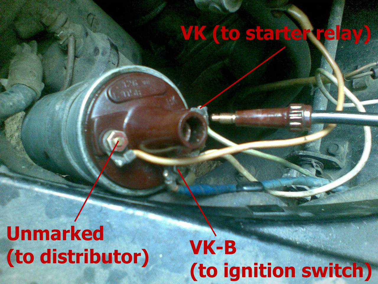
Find a 12V light bulb and a piece of wire (the manual recommends to use the under-hood engine compartment lamp, which is already connected to ground). Connect the bulb’s negative terminal to ground (-12V), and its positive terminal to the unmarked terminal of the ignition coil:
Now, turn the distributor housing clockwise (that is, backwards) very, very slowly and carefully and be ready to stop turning as soon as the bulb goes on ! If you skip the moment, you’ll have to start this operation from the beginning.
Hold the distributor in this very position and tighten the distributor hold down bolt (26).
Reassemble the whole thing and start the engine. Everything should work just nicely.
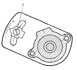
Some additional adjustment may be required from time to time, depending on driving conditions, the quality of fuel you use, etc. These minor adjustments are done by loosening the minor adjustments bolt (30) and rotating the distributor housing very slightly. There is a scale on the distributor base plate which is used to measure the correction of ignition timing (we have set it to Zero during our adjustment). Each division of the scale is equal to 2° of correction (in crankshaft degrees). Turn the distributor clockwise, so that the pointer is closer to “+”, to further advance the ignition timing, and counter-clockwise to retard it (that’s technical term, not an insult).
Experienced drivers often made minor tweaks to ignition timing “by ear” – listening for detonation (engine knocking) under acceleration. The manual recommends to slam hard on the accelerator pedal while moving at steady 30…35 km/h in fourth gear, and states that the ignition timing is set correctly if the detonation in these circumstances is slight and short (lasts no more than 3…4 seconds). Longer or severe detonation means that the ignition timing is too far advanced and should be slightly retarded – one division of the scale at a time until everything works as it should. No detonation at all means that the ignition is too far retarded (and that’s as bad as it sounds – the car would feel sluggish, have poor throttle response, etc.).
Needless to say that, if you so desire, you absolutely can make this adjustment with the use of an ignition timing light.
402 / 4021 engine (electronic ignition):
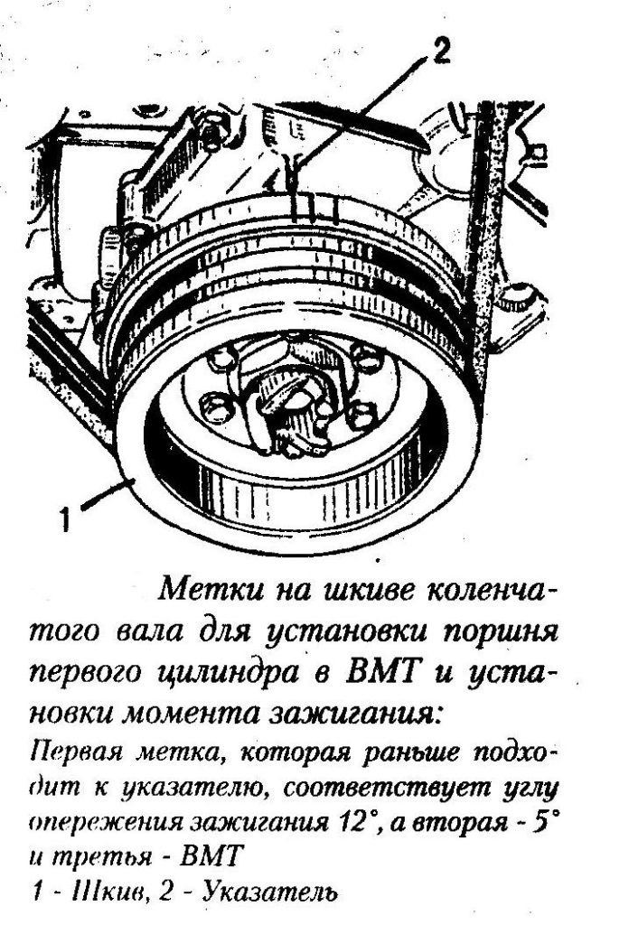
The crankshaft pulley is depicted in TDC position on this drawing.
Here we have three marks – the right-most one is 12 degrees BTDC, the middle one is 5 degrees BTDC, and the last on is TDC.
The procedure is mostly the same, but simpler as there are no points to adjust – hence the name “electronic point-less ignition system”, and we also won’t have to use the bulb.
Just as before, find the beginning of the compression stroke and continue turning the crankshaft until the 5 degrees notch is lined up with the pointer needle.
Set the scale to Zero by loosening the minor adjustments bolt, then tighten it.
Loosen the distributor hold down screw slightly, grab the distributor housing, and turn it…
…until the red line on the distributor rotor is in line with the pointer.
Tighten the hold down screw, and you’re done !
Just as with the point-type ignition system, some additional minor tweaks made “by ear” may be required to achieve the best performance.
However ! Be warned that this only works on the engines with a functional EGR (exhaust gases re-circulation; emissions control) system. This system mixes some of the exhaust gases into the air-fuel mixture; more timing advance is required for the engine to work properly in this case, and the distributors were calibrated with this in mind.
All 402 model engines (high-compression) with K-151 model carburetors did have EGR system from factory. 4021 engines (low-compression) and 402 engines with K-126M carburetors did not. However, EGR is typically no longer functional on most of these engines anyway, because most owners just plugged it.
For the engines that do not have EGR, the manual recommends to set the initial timing advance at 2 degrees BTDC instead of five degrees to compensate for the distributor calibration. That is roughly between the second (middle) and the third notches on the pulley.
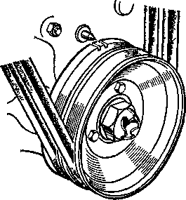
And the second problem you may encounter. The 402 and 4021 engines are equipped with a harmonic damper on the free end of the crankshaft. It helps to counter the vibrations somewhat, but may bring some additional troubles for the owner.
The damper is essentially a two-piece crankshaft pulley with a bonded rubber insert between the two halves. That’s all good and well, but eventually the rubber fails, and the two halves of the damper start to move mostly or completely independently:
And, naturally, the outer part of the damper that is held in place only by the bonded rubber is where the marks that you use to set the ignition timing are located…
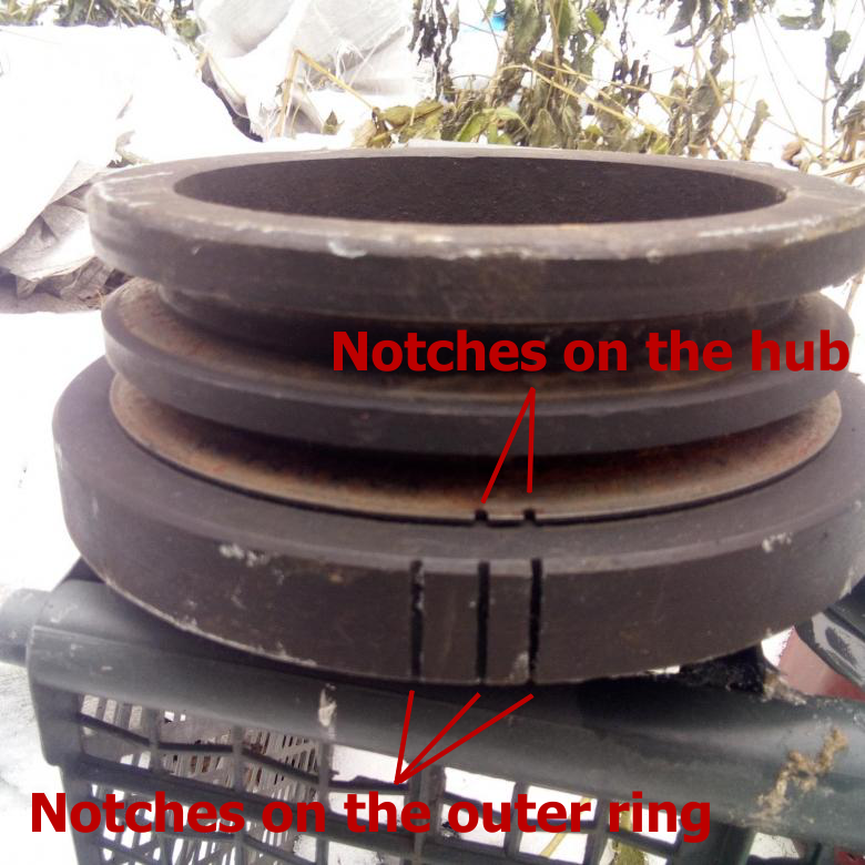
Luckily, the inner half of the damper (the hub), which is rigidly bolted to the crankshaft, usually also has two notches that correspond to 5 degrees BTDC and TDC. However, they are much less visible. If you use ignition timing light, they are almost unusable.
A special note must be made on the 2401 and 4021 engines, which have lower compression ratio and were originally designed to run on 76-octane (MON) A-76 gasoline. Today gas with such low octane rating is not available in most countries.
If you happen to own a car with one of these engines and low-octane gas is not available where you live, the best thing to do would be to mill the cylinder head, lowering its overall height by 3.5 mm (from the stock 98 mm to 94.5 mm). It is also often required to shorten the pushrods to be able to properly adjust the valve clearance, because if you use a milled head with the longer pushrods, the adjustment screws may be insufficient (stock “76-octane” pushrods are 287 mm long, “92-octane” pushrods are 283 mm). These modifications will allow the engine to work on 92 or 95 octane (RON) gas as if it was designed for it, without any further adjustments.
However, if you do not want to do that for the sake of originality of the car, you still can use 92 octane gas, but will have to advance the ignition by roughly 4 degrees (crankshaft), which is equal to one division of the “octane correction” scale towards “+”.
Some more quirks of the GAZ-24 ignition system. The original B-115 model ignition coil uses a screw-in high tension wire that has a male threaded connector at its end:
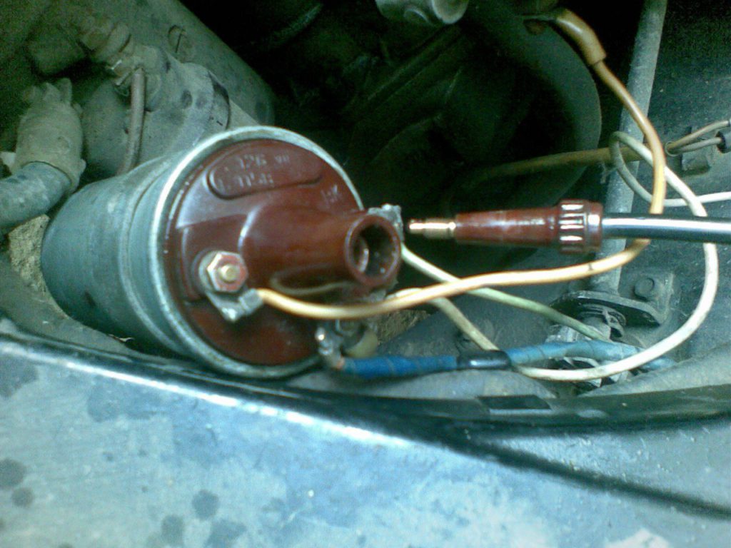
It is a very secure and reliable way of attaching the wire to the coil, but it makes this model of coil incompatible with most modern aftermarket wires. Copper core wires can be modified to fit this coil by soldering one of the ends of the core to the original connector. However, most modern ignition wires have carbon core and cannot be modified this way. Your options are: either stick with copper-core wires, or replace the ignition coil with a more modern one.
The B-115V model ignition coil (found in UAZ vehicles), on the other hand, uses a modern style coil wire, and can replace the original B-115 coil without any modifications. B-116 model coil, that is used in the point-less ignition system of the GAZ-24-10 and other later Volga models, works fine with modern wires as well (but can not be retrofitted into the old point-type ignition system).